Saturday, 14 December 2019

Shallow Copy

Following is the example of "Shallow copy".

class A;
  int var_i;
 
  function new();
    $display("Class A is created.");
  endfunction
 
  function void display(string inst_name = "");
    $display ("%0s:: Value of var_i=%0d", inst_name, var_i);
  endfunction
endclass // class A

class B;
  int var_j;
  A a_inst;
 
  function new();
    $display("Class B is created.");
    a_inst = new();
  endfunction
 
  function void display(string inst_name = "");
    $display ("%0s:: Value of var_j=%0d", inst_name, var_j);
  endfunction
endclass // class B

module top();
  initial begin
    B b_inst1, b_inst2;
    b_inst1 = new();
    b_inst1.var_j = 10;
    b_inst1.a_inst.var_i = 20;
    b_inst2 = new b_inst1;
    b_inst1.display("b_inst1");
    b_inst1.a_inst.display("b_inst1.a_inst");
    b_inst2.display("b_inst2");
    b_inst2.a_inst.display("b_inst2.a_inst");

    b_inst1.var_j = 30;
    b_inst1.a_inst.var_i = 40;
    $display ("Value of b_inst1.var_j changed to 30.");
    $display ("Value of b_inst1.a_inst.var_i changed to 40.");
    b_inst1.display("b_inst1");
    b_inst1.a_inst.display("b_inst1.a_inst");
    b_inst2.display("b_inst2");
    b_inst2.a_inst.display("b_inst2.a_inst");
  end
endmodule


Following is the result of the above simulation:
b_inst1:: Value of var_j=10
b_inst1.a_inst:: Value of var_i=20
b_inst2:: Value of var_j=10
b_inst2.a_inst:: Value of var_i=20

Value of b_inst1.var_j changed to 30.
Value of b_inst1.a_inst.var_i changed to 40.

b_inst1:: Value of var_j=30
b_inst1.a_inst:: Value of var_i=40
b_inst2:: Value of var_j=10
b_inst2.a_inst:: Value of var_i=40

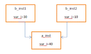
In the above code, statement "b_inst2 = new b_inst1", creates a shallow copy for instance "b_inst2". That means, creating a new object "b_inst2" whose class properties are copied from the object "b_inst1". All the class variables and instance handles are copied from "b_inst1" to "b_inst2". However, the instance handles within "b_inst1" and "b_inst2" points to the same object as shown in the below image, though new() is written for that instance handles.


I hope this post helped to understand shallow copy. Please provide feedback/suggestions in the comment section.
Friday, 6 September 2019

Difference between Wire and Logic data types in System Verilog.


WIRE:

1) If "wire" left unconnected then it shall have value 'Z.

2) "wire" acts as a physical connection between different elements and it doesn't store any values.
   For example, wire a = b; statement connects "b" element to "a" element.

3) "wire" can be used in module ports and in fact module ports default type is "wire".

4) If multiple drivers are driving to a "wire" element through continuous assignment("assign" statement) than the result would be 'X. Therefore multiple drivers/race condition produce undefined output value on "wire" type element.

Following is the example that shows race condition in case of multiple drivers are driving different value to a "wire" element.

module top();
  bit[1:0] drv1=1, drv2=2;
  wire[1:0] wire_type;

  // MULTIPLE DRIVERS 
  assign wire_type = drv1;
  assign wire_type = drv2;
   
  initial begin
    repeat(4) begin
      $display("Value of wire_type = %0h at time = %0tns", wire_type, $time);
      #5ns;
    end
    $stop();
  end
endmodule

RESULT:
Value of wire_type = X at time = 0ns
Value of wire_type = X at time = 5ns
Value of wire_type = X at time = 10ns
Value of wire_type = X at time = 15ns

5) "wire" cannot be driven in a procedural block. An example is stated below with the simulation result.

module top();
  bit clk;
  bit[1:0] drv1=1, drv2=2;
  wire[1:0] wire_type;

  always #5ns clk = ~clk;

  //MULTIPLE DRIVERS
  always @(posedge clk) wire_type =drv2;
  always @(posedge clk) wire_type =drv1;

  initial begin
    repeat(4) begin
      $display("Value of wire_type = %0h at time = %0tns", wire_type, $time);
      #5ns;
    end
    $stop();
  end
endmodule

RESULT:
Error-[IBLHS-NT] Illegal behavioral left hand side
testbench.sv, 16
  Net type cannot be used on the left side of this assignment.
  The offending expression is : wire_type
  Source info: wire_type = drv2;


Error-[IBLHS-NT] Illegal behavioral left hand side
testbench.sv, 17
  Net type cannot be used on the left side of this assignment.
  The offending expression is : wire_type
  Source info: wire_type = drv1;


LOGIC:

1) If "logic" left unconnected then it shall have the value 'X.

2)  "logic" can be driven by a continuous assignment ("assign" statement), in module ports or inside a procedural block.

3) Multiple drivers to the "logic" element in continuous assignments do not allow. 
For example: 
  assign logic_type = drv1;
  assign logic_type = drv2;
In above case, simulator shout errors for multiple drivers.

4) In case multiple drivers are driving different values to a "logic" element in procedural blocks then the "logic" element simply assigns the value from the last assignment.

Below is the example with the simulation result.

module top();
  bit clk;
  bit[1:0] drv1=1, drv2=2;
  logic[1:0] logic_type;

  always #5ns clk = ~clk;
  
  //MULTIPLE DRIVERS
  always @(posedge clk) logic_type = drv2;
  always @(posedge clk) logic_type = drv1;

  initial begin
    repeat(4) begin
      $display("Value of logic_type = %0h at time = %0tns", logic_type, $time);
      #5ns;
    end
    $stop();
  end
endmodule

RESULT:
Value of logic_type = X at time = 0ns
Value of logic_type = X at time = 5ns
Value of logic_type = 1 at time = 10ns
Value of logic_type = 1 at time = 15ns


I hope the above points related to "wire" and "logic" will help to understand the difference between both of them. If you any comment or feedback, please in the comment box. 

Friday, 30 August 2019

What is m_sequencer and p_sequencer in UVM?

In this post, I am trying to explain the difference between m_sequencer and p_sequencer in UVM and their usage.

Firstly, let's look for the details about m_sequencer's type, it's scope and role. Basically, m_sequencer is the sequencer on which our sequence will run. In other words, it is the default sequencer and it will point to the user sequencer's handle on our test bench. Let's look at how it is pointing to the test bench's user sequencer.


From the above image, we can see that the m_sequencer instance type is "uvm_sequencer_base" and an instance is taken in the "uvm_sequence_item" class, therefore it is visible to any user sequence. Type of m_sequencer is "uvm_sequencer_base".

If the user sequence has "`uvm_declare_p_sequencer" macro then this macro defines p_sequencer handle whose type will be user_seqr. If this macro is not declared in the user sequence then p_sequencer does not exist.

So, when "user_seq.start(user_seqr)" method gets execute from the test then "set_sequencer()" method gets invoked and user_seqr(child class) handle will be assigned to uvm_sequencer_base(parent class) handle i.e. m_sequencer. Further "m_set_p_sequencer()" method gets execute if "`uvm_declare_p_sequencer" is declared in the user sequence which casts  m_sequencer(parent class uvm_sequencer_base's handle) to p_sequencer (child class user_seqr's handle) to check type compatibility.

In summary, m_sequencer is uvm_sequencer_base type and will point to the user sequencer when the user sequence is initiated. Whereas p_sequencer is user sequencer type when macro "`uvm_declare_p_sequencer" is declared in user sequence. I hope this post will help to understand m_sequencer and p_sequencer.

Monday, 29 April 2019

What is Polymorphism?

In this post, I am going to explain very basic details about Polymorphism with an example. Basically, Polymorphism is used to redefine or extend the methods of the base classes and this can be achieved by overriding the base class methods using the methods defined in the derived classes. Following are some of the rules to be taken care for Polymorphism.
1) Place "virtual" keyword with method definition in base class which will to be redefined in child class.
2) Method name, number of arguments in the method and type of arguments in the method should be same as base class method in order to override base class method with derived class method.

Let's take an example of method overriding and see the results.

class base;
  virtual function void display();
    $display("BASE Class display method.");
  endfunction 
endclass

class child extends base;
  function void display();
    $display("CHILD Class display method.");
  endfunction 
endclass

module top();
  initial begin
    base b1;
    child c1;
    c1 =new();
    b1 = c1;
    b1.display();
    c1.display();
  end
endmodule

RESULT:
CHILD Class display method.

If we remove "virtual" keyword from the base class "display()" method definition then base class method will not get overridden and following is the result.

RESULT:
BASE Class display method.
CHILD Class display method.

Monday, 15 April 2019

Wrapping Burst in AXI

In this post, I am going to give some basic details of the AXI WRAP Burst and how to calculate the WRAP boundary. First of all, there are few rules that need to be considered for WRAP Burst, which is stated below.
1) The start address must be aligned to the size of each transfer or in other word, aligned to AxSIZE
2) The Burst length must be 2, 4, 8 or 16 transfers.

Let's understand using one example. Assume, Burst length = 4, Burst size = 1(2 Bytes Data bus width) and Start_Address is 0x24(Aligned to AxSIZE).

First of all, we need to calculate the WRAP boundary using the below equation.

Wrap_Boundary = (INT(Start_Address/(Number_Bytes*Burst_Length))) * (Number_Bytes*Burst_Length)
                           = (INT(36/(2*4))) * (2*4)
Wrap_Boundary = 0x20

In WRAP burst, during any write/read request address gets increment the same as the INCR burst. Now the question is when actual wrapping will take place? So, for a WRAP burst, if (Start_Address_N  == Wrap_Boundary + (Number_Bytes * Burst_Length)) then wrapping will occur i.e. Start_Address_N = Wrap_Boundary.

For the above example, write/read request address increments following way

Start_Address_0 = 0x24
Start_Address_1 = 0x26
Start_Address_2 = 0x20(Wrap_Boundary)  (Why?
Because Start_Address_2 = 0x28 satisfies the equation "Start_Address_N  == Wrap_Boundary + (Number_Bytes * Burst_Length)" and so, Start_Address_2 = 0x20(Wrap_Boundary).)
Start_Address_3 = 0x22

If you have any comments or feedback, please leave it in the comment box. Thank you for reading this blog.

Friday, 12 April 2019

What is Burst Length and Burst Size in AXI Protocol

Burst length

Burst length in AXI is the number of transfers for the Read/Write. AXI3 supports burst lengths of 1 to 16 transfers for all burst types (FIXED, INCR and WRAP). AXI4 extends burst length support for INCR burst type to 1 to 256 transfers and remains burst length to 1 to 16 transfers for all other burst types(FIXED and WRAP).

Signal for read transfers -> ARLEN[7:0]
Signal for write transfers -> AWLEN[7:0]

Burst length for AXI3 and AXI4 Write/Read transfer defined as,
Burst length = AxLEN[3:0] + 1
Burst length for INCR burst type of extended AXI4 Write/Read transfer defined as,
Burst length = AxLEN[7:0] + 1

Above definition explains that, AxLEN[3:0] = 0 means burst length is 1, same way AxLEN[7:0] = 255 means burst length is 256.

One rule about burst lengths of wrapping bursts is, its burst length must be 2, 4, 8 or 16.

Burst size

 Burst size is the maximum number of bytes can be transfer in a burst or transfer or a beat. Burst size is nothing but data bus width.

Signal for read transfers -> ARSIZE[2:0]
Signal for write transfers -> AWSIZE[2:0]

Encoding of AxSIZE[2:0] is pasted below.


Total number of transferred bytes can be calculated as, (Bytes in transfer) * (Number of transfers).